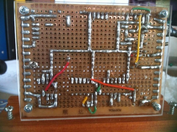
My Father loves clocks and anything that reports the temperature (and other weather related info). So for Xmas 2010 I built this little piece to add to his collection.
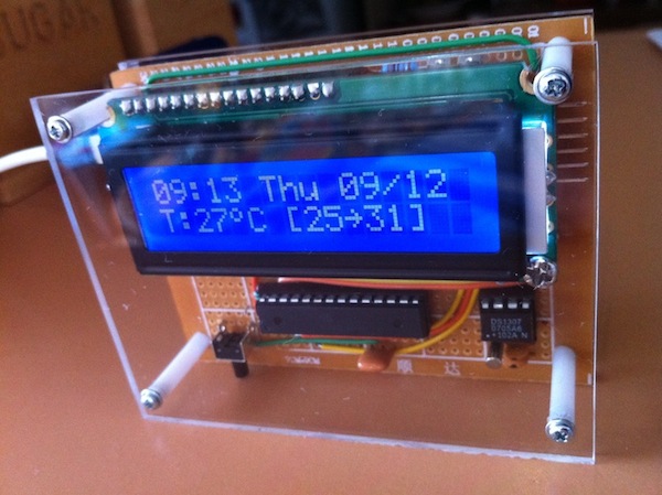
It uses a DS1307 with backup battery to track time, and a LM35 for recording the temperature. The LCD displays time, date, current temperature and min and max recorded temperatures (which are backed up in EEPROM). The button at the bottom of the board is used to reset the min/max values. Also I included a serial connection so the sketch can be updated, and also a little serial protocol so the time can be adjusted if required. I used an iPod power supply for nice clean 5V supply - which I modded to use a 2-pin connector to attach to the board.
I also added a bunch of canned messages for specific dates, Xmas, NY, birthdays etc.
Finally presented it to him along with a laminated version of the schematic I created. He loved it!
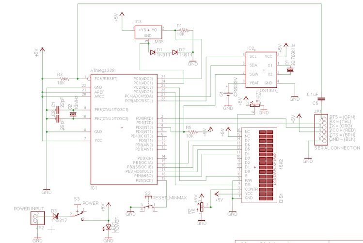
  Conn   Funct Arduino  ATmega328      Arduino Funct Conn
                      +-----\/----+
         Reset       1| PC6   PC5 |28  D19 A5  SCL  DS1307 SCL
  FTDI   Rx    D0    2| PD0   PC4 |27  D18 A4  SDA  DS1307 SDA
  FTDI   Tx    D1    3| PD1   PC3 |26  D17 A3       LCD_RS
  SQW    Int0  D2    4| PD2   PC2 |25  D16 A2       LCD_E
         Int1  D3    5| PD3   PC1 |24  D15 A1       LM35 GND REF
               D4    6| PD4   PC0 |23  D14 A0       LM35 VO
                     7| VCC   GND |22
                     8| GND  AREF |21
         Xtal        9| PB6  AVCC |20
         Xtal       10| PB7   PB5 |19  D13     SCK  RESET MIN/MAX
         OC0B  D5   11| PD5   PB4 |18  D12     MISO LCD_D4
         OC0A  D6   12| PD6   PB3 |17  D11     MOSI LCD_D5
               D7   13| PD7   PB2 |16  D10          LCD_D6
               D8   14| PB0   PB1 |15  D9           LCD_D7
                      +-----------+

                          DS1307       ATMega
                      +-----\/----+
             Xtal    1| X1    VCC |8   VCC
             Xtal    2| X2    SQW |7   D2/Int0
           3V Bat    3| VBAT  SCL |6   D19/SCL
              GND    4| GND   SDA |5   D18/SDA
                      +-----------+

 FTDI 6-Pin Connector from top of board:
 *-- RTS (GRN) --> 0.1uF cap --> PC6 (RESET)
 *-- RX  (YEL) --> TX
 *-- TX  (ORG) --> RX
 *-- VCC (RED) --> VCC
 *-- CTS (BRN) --> GND
 *-- GND (BLK) --> GND